Plc Traffic Light Program
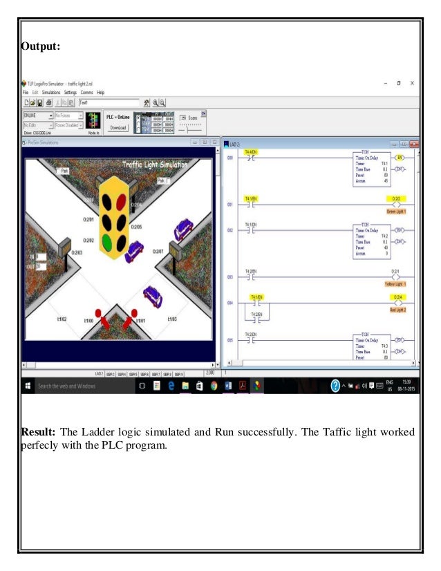
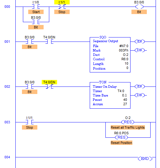
The previous traffic light example is to be implemented in ladder logic. The inputs and outputs are defined in Figure 11.9 Inputs and Outputs for Traffic Light Controller, assuming it will be implemented on an Allen Bradley Micrologix. First scan is the address of the first scan in the PLC. Due to a request I wrote this ladder diagram for a traffic light and tested it on my S7200 plc. Program 2: TRAFFIC SIGNAL PROGRAM When start press RED signal ON for 10 second and OFF, then after YELLOW signal ON for 10 second and OFF, then after GREEN signal ON for 10 second and OFF.

Traffic Light Panel Plc Programming
Here is PLC program to Control Traffic Lights, along with program explanation and run time test cases. Ladder Diagram to control Traffic Light. In part 1 we looked at writing PLC programs to control a traffic light using discrete bits and then using timed sequencing using indirect addressing. We will now look at how we can use indirect addressing for inputs as well as output to control the sequence in the program. Students have to write a PLC program starting from a single traffic light operation, adding later multiply traffic lights and include pedestrian lights and extending PLC program to include external control for emergency such as fire and ambulance.

Traffic light Simulation: Traffic light program in C presents what happens in our daily life at traffic light signals. Firstly user will press a key to start the traffic light simulation.
C programming code
- #include<conio.h>
- #include<stdlib.h>
- main()
- int gd = DETECT, gm, midx, midy;
- initgraph(&gd,&gm,'C:TCBGI');
- midx = getmaxx()/2;
- settextstyle(SCRIPT_FONT, HORIZ_DIR,3);
- outtextxy(midx, midy-10,'Traffic Light Simulation');
- outtextxy(midx, midy+10,'Press any key to start');
- cleardevice();
- settextstyle(DEFAULT_FONT, HORIZ_DIR,1);
- circle(midx, midy-50,22);
- floodfill(midx, midy-50,WHITE);
- outtextxy(midx,midy-50,'STOP');
- graphdefaults();
- setcolor(WHITE);
- circle(midx, midy,20);
- floodfill(midx, midy,WHITE);
- outtextxy(midx-18,midy-3,'READY');
- delay(2000);
- setcolor(WHITE);
- circle(midx, midy+50,22);
- floodfill(midx, midy+50,WHITE);
- outtextxy(midx-7,midy+48,'GO');
- settextstyle(SCRIPT_FONT, HORIZ_DIR,4);
- outtextxy(midx-150, midy+100,'Press any key to exit..');
- getch();
- return0;
Download Traffic Light Simulation. Worms ultimate mayhem.
Information on Drawing Numbers for Traffic Light PLC Program:
1. Red Color Lights in Position A
2. Green color lights in Position A
3. Red Color Lights in Position B
4. Green color lights in Position B
5. Red Color Lights in Position C
6. Green color lights in Position C
7. Red Color Lights in Position D
8. Green color lights in Position D
Number Of Inputs and Output PLC applied :
1. Number Of Inputs PLC is 1 Input :
--- 1 Unit Input for Switch ON/OFF Traffic Light.
--- Total Number Of Inputs PLC is Minimum 1 Input Unit.
2. Number Of Output PLC is 8 Output :
--- 1 Unit Output for Red Color Lights in Position A
--- 1 Unit Output for Green color lights in Position A
--- 1 Unit Output for Red Color Lights in Position B
--- 1 Unit Output for Green color lights in Position B
--- 1 Unit Output for Red Color Lights in Position C
--- 1 Unit Output for Green color lights in Position C
--- 1 Unit Output for Red Color Lights in Position D
--- 1 Unit Output for Green color lights in Position D
--- Total Number Of Outputs PLC is Minimum 8 Output Unit.
Sequence PLC Programming for Traffic Light PLC Program:
Step 1 :
a. If Switch ON/OFF = ON Then System Traffic Light is Active.
b. If Switch ON/OFF = OFF Then System Traffic Light is Inactive.
Step 2 :
a. IF Green color lights in Position A ( No.2) = ON then Red Color Lights in Position B,C, AND D = ON And Timer0 Activated.
b. IF Timer0 = ON then Green color lights in Position C ( No.6) = ON And Red Color Lights in Position A,B, AND D = ON And Timer1 Activated.
c. IF Timer1 = ON then Green color lights in Position D ( No.8) = ON And Red Color Lights in Position A,B, AND C = ON And Timer2 Activated.
d. IF Timer2 = ON then Green color lights in Position B ( No.4) = ON And Red Color Lights in Position A,C, AND D = ON And Timer3 Activated.
e. IF Timer3 = ON then Green color lights in Position A ( No.2) = ON And Red Color Lights in Position B,C, AND D = ON And Timer0 Activated.
f. Continuously to Step 2.b
g. Timer0,1,2,3 set to 2 minutes
Download Simulation Traffic Light :
Please Click : Traffic Light PLC Program
Can You make Program Ladder PLC ?
If Can't :
Traffic Light PLC Program with PLC Omron
Traffic Light PLC Program with PLC Mitsubishi
Traffic Light PLC Program with PLC Keyence